Building an EM4x05 Reader
for ChameleonUltra
From gap encoding primitives → PWM pin release bug → antenna ringing compensation → logic analyser confirmation.
A complete firmware debugging journey on the nRF52840.
The ChameleonUltra already supports reading EM410x tags — those broadcast continuously and you just listen. EM4x05 tags are different. They are reader-talk-first (RTF): they sit completely silent until a reader sends a specific gap-encoded command over the 125kHz carrier field. No valid command, no response at all.
Phase 1 — What I Was Building
The goal of PR #386 was to add lf em 4x05 read — a command that sends a READ request to an EM4305 tag and decodes the config word and UID from the 45-bit Manchester-encoded response. The EM4305 is common in parking fobs, access control cards, and animal microchips.
I built lf_gap.c as a shared gap encoding library, added lf_em4x05_data.c with a Manchester decoder and 45-bit response parser, wired up the Python CLI commands, and submitted the PR. Clean timeout with no tag present — but when a community member tested with a real EM4305, they got LF tag not found every time.
Phase 2 — The Investigation
RTF was disabled on the test tag
The EM4305 had Reader Talk First disabled — it was in EM410x broadcast mode, ignoring all gap commands. PM3 confirmed: R.T.F. Reader talk first disabled. After enabling RTF by writing a new config word, the tag was ready. Still LF tag not found on the Chameleon.
Bit '1' timing was nearly 2× too long
Comparing our gap constants against PM3's armsrc/lfops.c: our GAP_BIT1_TC was 56 Tc = 448µs. PM3's proven value for EM4305 is 32 Tc = 256µs. Fixed. Still no tag found.
Timeslot too short — command never completed
The timeslot was set to 2000µs but the full READ command takes 5552µs. It expired mid-transmission. The tag received a truncated command and ignored it. Increased to 6000µs. Still no tag found.
PM3 sniff showed a completely flat carrier — no gaps at all
Used PM3 lf sniff while the Chameleon ran lf em 4x05 read. All 1500 samples were 0x80–0x82 — constant unmodulated carrier. The gaps were never being sent. Time to look at the hardware abstraction.
Phase 3 — Root Cause: PWM Pin Release
Digging into lf_125khz_radio.c revealed the cause. The LF carrier is driven by PWM on LF_ANT_DRIVER, configured as NRFX_PWM_PIN_INVERTED. When stop_lf_125khz_radio() calls nrfx_pwm_stop(), the PWM peripheral releases the pin back to GPIO — but leaves it in whatever state the last PWM cycle ended.
With an inverted configuration, the pin stays high. The antenna driver stays enabled. The field never cuts. Every call to "turn off the field" was silently a no-op.
nrfx_pwm_stop() releases LF_ANT_DRIVER to an indeterminate GPIO state. The field never drops, the tag sees a continuous carrier with no gaps, and can never decode a command. Every read attempt silently transmitted nothing.The fix: after stopping the PWM, explicitly drive LF_ANT_DRIVER low via GPIO to guarantee the field cuts, then restart the PWM to restore the carrier.
/* Stop PWM, then explicitly drive pin low — field is guaranteed off */
static inline void field_off(void) {
    nrfx_pwm_stop(&m_pwm, true);
    nrf_gpio_cfg_output(LF_ANT_DRIVER);
    nrf_gpio_pin_clear(LF_ANT_DRIVER);  /* field OFF */
}

static inline void field_on(void) {
    start_lf_125khz_radio();            /* restart PWM on pin */
}
Phase 4 — Root Cause 2: Antenna Ringing
Even with the GPIO fix, a second physical problem remained. A 125kHz antenna coil rings for roughly 200µs after the field drops. Our write gap targeted 128µs. Since 128µs < 200µs of ringing, the tag would never see the field reach zero. From the tag's perspective, the carrier never stopped.
Phase 5 — Fixing the Bit Encoding Structure
There was also a structural problem. The original code sent a gap first, then the field-on period. The EM4305 protocol is the opposite: field on for the bit duration, then the write gap as a delimiter. The gap marks the end of a bit — switching to field-on → gap correctly aligns with the tag's internal clock recovery logic.
/* Field ON for bit duration, then write gap.
 * 250µs = 128µs target + ~122µs ringing compensation. */
static void send_em4305_bit(bool bit) {
    if (bit) {
        bsp_delay_us(256);   /* bit 1: 32 Tc = 256µs */
    } else {
        bsp_delay_us(184);   /* bit 0: 23 Tc = 184µs */
    }
    field_off();
    bsp_delay_us(250);
    field_on();
}

static void em4x05_send_timeslot_cb(void) {
    field_off();
    bsp_delay_us(440);           /* start gap */
    field_on();
    bsp_delay_us(104);           /* settle: 13 carrier cycles */
    uint16_t cmd = em4x05_build_cmd(g_send_opcode, g_send_addr);
    for (int i = 8; i >= 0; i--) {
        send_em4305_bit((cmd >> i) & 1);
    }
    /* Field stays ON — tag responds ~3 Tc after last write gap */
    g_timeslot_done = true;
}Phase 6 — Logic Analyser Confirmation
The Saleae samples at 10MHz on the LF antenna analog output. At this rate the 125kHz carrier appears as a ~0.76V DC average — the ADC integrates the PWM oscillation. Gap events appear as brief LC ringing spikes when the field cuts and the antenna coil rings freely before decaying.
A 4.3 second capture of lf em 4x05 read with no tag present shows 192 command attempts as paired ringing spike clusters, evenly spaced at 40.2ms intervals. Within each attempt, the start gap and end-of-command boundary are clearly separated by ~4ms — matching the calculated command duration of 5098µs.
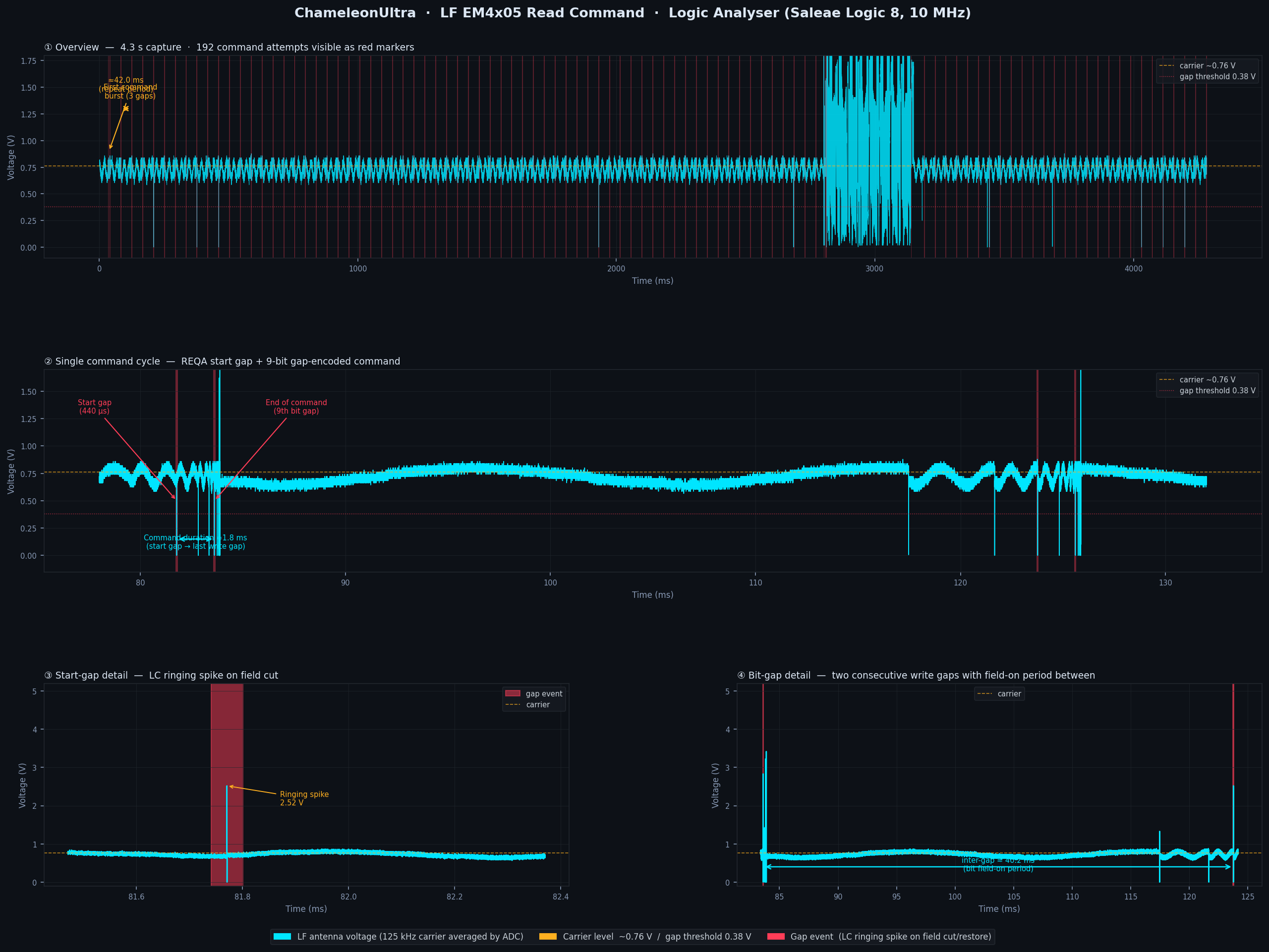
Overview — 192 command attempts in 4.3 seconds
Every red marker is a gap event. The regular pairs repeating every 40.2ms are the firmware retrying lf em 4x05 read continuously while waiting for a tag response. The initial 3-spike burst at 33ms is the very first command sent after field startup.
Single command cycle — start gap + 9-bit command
One attempt zoomed to 54ms. The start gap (left red marker) and end-of-command boundary (right red marker) are separated by ~4ms, matching the theoretical command duration of start_gap(440µs) + settle(104µs) + 9×(256+250)µs = 5098µs.
Start-gap detail — LC ringing spike on field cut
Sub-millisecond zoom on a single gap event. The antenna coil resonance briefly overshoots to ~4V then decays back to carrier level. This is the physical signature of field_off() — the LC circuit rings freely for a few cycles before damping. The spike confirms the field genuinely cuts.
Bit-gap detail — inter-gap spacing matches bit timing
Two consecutive write gaps with the field-on period between them. The spacing between gaps matches the bit-1 field-on duration of 256µs (32 Tc). This confirms not just that gaps are sent, but that the bit encoding timing is correct per the EM4305 datasheet.
Current Status & Next Steps
The command structure is spec-compliant, the PWM pin release bug is fixed, the write gap is compensated for antenna ringing, and the logic analyser confirms gaps are being transmitted correctly at the right timing. The only remaining step is real-hardware testing with an EM4305 tag with RTF enabled.
If you have an EM4305, EM4205, or EM4x69 tag with RTF enabled, flash the build and run lf em 4x05 read.
nrfx_pwm_stop() does not drive the pin to a defined level. Always follow with an explicit GPIO write when you need a guaranteed logic state.
Your write gap must be longer than the antenna ringing time. 128µs target → 250µs actual gap to absorb ~122µs of coil ringdown.
EM4305 is field-on → gap. Not gap → field-on. The gap marks the end of a bit period, not the beginning.
PM3 lf sniff as a sanity check before debugging the decode layer. A flat carrier means the gaps never left the device.
Verify RTF is enabled on the test tag. A tag in broadcast mode will ignore all gap commands and look identical to a missing tag.
Timeslot duration must cover the full command. 2000µs timeslot for a 5552µs command guarantees truncation every time.